Real-time 3-D ultrasound imaging system using 2-D ring array probe
ˇˇ
Intravascular 3D forward viewing is important for clinic diagnosis such as for angiostenosis. Conventional viewing method using a glass fiber endoscope cannot obtain any forward view due to the blood filled in the blood vessel. Ultrasonic imaging technique is useful in this forward viewing case. Therefore, we had developed the special ultrasonic probe which is called "the ring array probe", and the measurement method using synthetic aperture beamformig called "the Instantaneous Frontal Imaging Method. It is possible to reconstruct 3-D images in real-time because this method requires no scanning. However, there is no real-time ultrasound 3-D imaging system because the image was reconstructed after the measurement data was stored in the digital oscilloscope. Therefore, in this paper we built a system for real-time 3D imaging.
ˇˇ
The one transducer transmits a spherical wave to a measurement region. The object reflects ultrasound, and All transducers of the probe receive one. The propagation times of the ultrasound are different in each transducer. Therefore, the position of the object can be recognized from these differences. Thus, this probe can measure frontal 3-D objects rapidly without scanning.
This measurement time is 2D/C, where D is maximal depth of measurement region and C is the speed of wave propagation, and it is thus possible to acquire the echo data in a very short time. In fact, data acquisition time of a 3-D data set is about 40 ¦Ěs, where D = 30 mm and C = 1500 m/s. Thus images can be acquired at a rate of about 25000 images/s by this method.
Therefore, measurement in real time is possible because this measurement rate is fast enough to freeze object motion or probe motion. For example, assuming a maximum motion speed of about 20 mm/s, the object or the probe will move no more than 20 ¦Ěs during the collection of one 3-D data set. This measurement method is equivalent to a synthetic aperture beamforming.
ˇˇ
The 3-D image reconstruction described as follows.
ˇˇ
ˇˇ
4. 2-D ring array probe
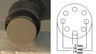
The probe used for measurement is the ring array probe of a diameter 16mm. 8 transducers which diameter is 2mm are arranged on the circle of 10mm. (Fig.1) One of the transducers transmitted a spherical pulsed wave and the other 7 ones received the echo
.
Figure 1
5. System
Figure 2 shows the experimental system consisting of the 2-D ring array probe, a pulse generator (Hewlett Packard 8116A), an amplifier, an A/D converter (Circuit Specialists PCI9812), and a personal computer (Dual pentium3 Xeon 550MHz). The system works as follows.
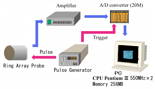
Figure 2
ˇˇ
6. Experiment(measurements of swinging iron ball)
To evaluate frame rate and lateral resolution, a swinging iron ball (11mm in diameter) was measured in water in Fig.3. The iron ball was located at the center of probe and 30 mm from the surface of the ring array probe.The parameters of the experiment are shown in Table 1.
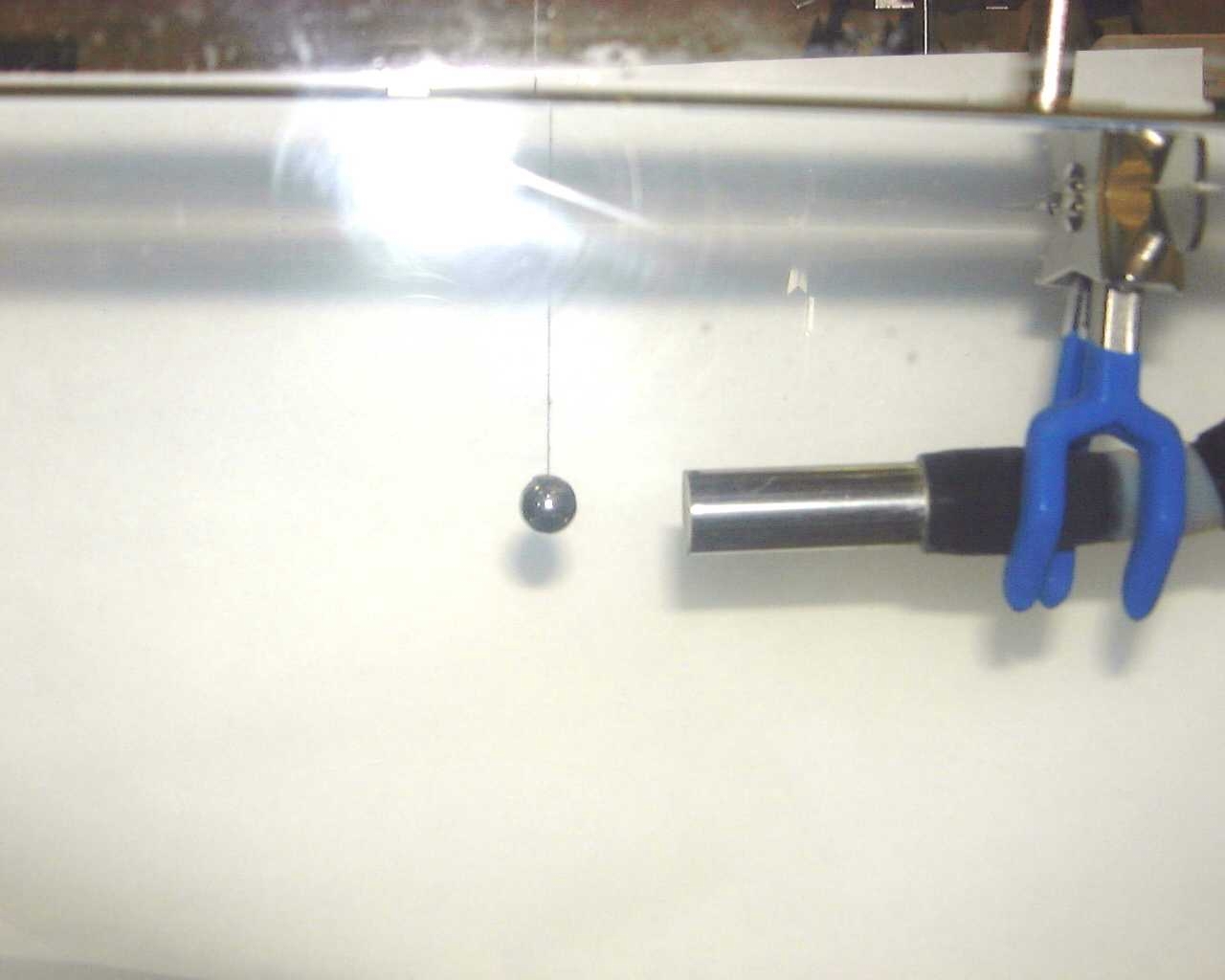
Figure 3
ˇˇ
|
environment |
in water |
|
velocity of sound |
1482.7 m/s |
|
central frequency |
5 MHz |
|
sampling frequency |
20 MHz |
|
pulse repetition time |
1 ms |
|
number of transducers |
8 |
|
diameter of the probe |
16 mm |
|
discretized elements |
0.6 mm/pitch (20 * 20 * 40) |
Table 1:the parameter of experiment
ˇˇ
ˇˇ
7. Results
Figures.4 and 5 shows results of experiment1.

Figure 4:Front view
ˇˇ

Figure 5:Side view
7-1. Frame Rate
Because display requires large cost, if the system did not display, reconstruction rate was 40 times/s. However, the actual frame rate was only 13 frame/s.
ˇˇ
7-2. Spatial resolutions
As seen in Fig.5, this system showed a good axial resolution, but lateral resolution was not good because of many elliptically artifacts in Fig.4.
ˇˇ
8. Conclusion
We built real-time 3-D ultrasound imaging system using 2-D ring array probe. The experimental results obtained using an iron ball and a plastic case show that real-time 3-D measurement is possible. The frame rate of this system was 13 frames/s. Since the lateral resolutions can be improved, our system would be very effective for clinical use. In the future, We will experiment with small diameter probe (2mm in diameter) for measurement inside blood vessel.
ˇˇ
ˇˇ