Measurment Methods of Shape and Refractive Index of Transparent Objects by Changing Patterns
-
INTRODUCTION
-
APPROACH
-
EXPERIMENT
-
CONCLUSION
INTRODUCTION
Various real objects are digitalized, and the developed techniques of computer graphics (CG) have made possible high reality representation of the digitalized objects. However it is difficult to represent real trans- parent objects because there are few measurement method of transparent objects. Therefore the transparent objects are represented by modeling based on CAD data.
Recently, the representation methods of the transparent objects based on image-based rendering are proposed for higher reality [1]. The method based on Image-based rendering can represent the transparent objects like a photograph, because this method uses acquired images from many view points while changing lighting condition. However this method only reproduces the transparent object at determined view points based on acquired images. As the solution of this problem, the character- ristics of the transparent objects like a shape or refractive index should be measured.
In general, there are two measurement methods of the shape of object. They are contact-type and non-contact-type methods. The contact-type method uses a contact probe to measures the shape of the object [2]. However this method can’t use for easily broken and soft objects.
On the other hand, the non-contact-type method almost measures the shape of the object using diffuse reflection of the object surface. For example, shape-from-shading [3] is the method of the shape measurement using shading information of target objects. Photometric stereo [4] uses some shading images with three different light position. Furthermore, a spot projection method, such as laser range sensor, measures the shape of objects by projecting a laser light, and a surface method, such as Moire topography [5], measures the shape of objects by projecting patterns like a grid.
These methods, however, cannot measure transparent objects like a crystal. These methods measure the shape of the object using diffuse reflection of its surface, but transparent objects cannot observe diffuse reflection. As the matters stands, these methods are not suitable for measuring the shape of the transparent objects.
Currently, as a method of shape measurement of the transparent objects, Miyazaki et. al. [6] have proposed a measurement method based on analyzing degree of polarization of surface reflection in visible and far infrared wavelengths, respectively. However this method needs refractive index of transparent objects, and cannot measure a shape of object if its refractive index is unknown.
This paper proposes a measurement method of shapes and refractive index of transparent objects with convex shape and uniform refractive index. This method measures the shape of transparent objects using the silhouette method, and it estimates the reflective index of the transparent objects using changing background patterns by refraction.
APPROACH
This paper aims the non-contact-type measurement method of a shape and a reflective index of a transparent object.
Non-contact-type measuring methods of the shape of objects almost use the diffuse reflection of the object surface, but they cannot measure the shape of transparent objects without diffuse reflection on the surface. Therefore our method uses a silhouette of the transparent object instead of the diffuse reflection on the object surface. The silhouette method using difference from background can measure the shape of transparent objects without using the diffuse reflection. And this method uses the change of background patterns by means of the characteristics of transparent objects, so this method can measure a transparent object that is unknown material.
The refractive index of transparent objects is determined using light passes and the shape of transparent objects. The light pass in transparent objects is extracted by means of investigating an appeared point on the surface that move from a background point by passing transparent object.
2.1 Shape from Silhouette
Shape from silhouette [6] is a method of shape measurement based on a sequence of silhouette taken the object from multiple viewpoints. First, the image of the object is acquired under a viewpoint, and a silhouette of the object is extracted from the acquired image. After rotating the object, like a turntable, a silhouette from a different viewpoint is extracted from the acquired image. Then the shape is represented from these silhouettes of the object. However in the case of transparent object, it is difficult to extract the silhouette of the object for uniform background. Our proposed method uses patterns on background.
When setting a transparent object in front of patterns, patterns change along silhouette of the transparent object. If the position of a transparent object is known, the silhouette of transparent objects is extracted by observing the difference between changing patterns and background patterns. And rotating the transparent object, each silhouette of the transparent object is acquired the difference from background, respectively. Finally, the shape of the transparent object is measured by integrating these silhouettes.
This proposed method acquires two type images, background images (figure 1: Left) and images including the transparent object as measured images (figure 1: Right). When computing difference between background images and measured images, we need accurately difference images. Therefore this method uses space coded images for fine difference images.
2.2 Refractive index
Kazama [7] has proposed a determination method of the refractive index of transparent object by means of extracting light passes to use corresponding points of background image and measured image (figure 1) and the shape of the transparent object. This method assumes the shape of the transparent object is known, and the refractive index is determined recursively. If assuming that light is parallel projection, the refractive index of the transparent object can be determined uniquely by light passes and the reproduced shape of the transparent object.
Figure 2 shows schematic of light pass from background to plane of camera. A is the corresponding point ofbackground image, P1 is the intersection point of the transparent object’s plane and starting light ray from A, and P2 is the point escaping light ray through the transparent object. Then the normal vector at P1 is denoted as N1, and the incident angle at P1 is denoted as θ1i. The incident angle θ1i is represented as
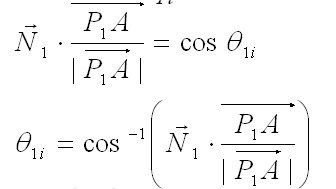
On the other hand, the refractive angle q1o is represented as
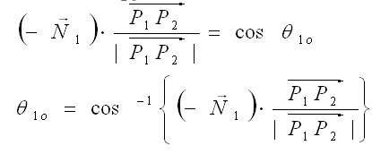
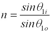
The refractive index n is calculated following Snell’s law using the incident angle θ1i and refractive angle θ1o as
Moreover the refractive index can be calculated using θ2i and θ2o same as above process.
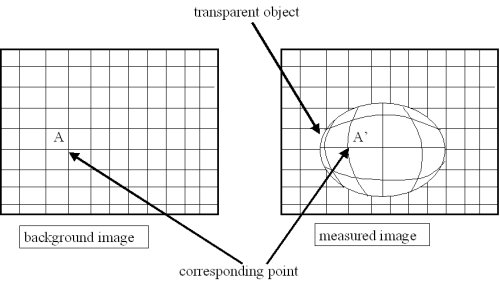
Fig.1:Corresponding point.
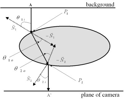
Fig.2:Light pass.
EXPERIMENT
In order to show effectiveness of this method, this paper has measured a spherical object of acrylic. Our proposed method uses the movement of a point to a position in measured image from a position in background image through the transparent object by refraction of light. The moving point is found by two-dimensional space encoding with the use of vertical and horizontal graycode patterns. When encoding the space, the graycode patterns can decrease error of transformation than binary patterns [9].
3.1 Experiment System
Figure 3 shows the experiment system. This system sets a turntable in front of a liquid crystal display. The liquid crystal display is used to display the graycode patterns as the background patterns. Furthermore a CCD camera is set in front of the turntable. The transparent object is set on the turntable. And the background images and measured images are acquired with CCD camera.
In this experiment, 8bit graycode patterns are used for the background images and measured images for one rotating angle of the transparent object. The rotating step is 10 degrees, so the silhouettes of the transparent object are measured at 36 positions
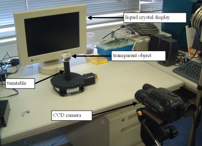
Fig.3:Experiment system.
3.2 Process of Shape from Silhouette
Figure 4 shows process of the shape measurement from silhouette. First 8bit graycode patterns displayed on light crystal display, and the background images and the measured images are acquired. The measurement space is encoded with the use of graycode patterns. The silhouette is extracted using the difference of the background image and the measured images. When extracting silhouette of a transparent object, space coded images are created from 8bit graycode patterns. If the silhouette is extracted at the position, the transparent object is rotated with the use of the turntable and the process is repeated. When the transparent object turns around, the shape of the trans-parent object is measured from integrating these extracted silhouettes.
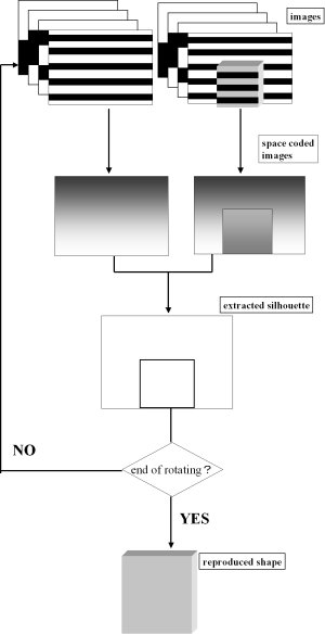
Fig.4:Process of shape from silhouette.
3.3 Result
Figure 5 is a reproduced shape of a spherical transparent object from the extracted silhouette. This result represents shape of a spherical transparent object, so this shape can be used with extracting the refractive index of the transparent object.
When the refractive index of transparent object is calculated using our method, the corresponding point between a background image and a measured image is necessary. Then the corresponding point is found by encoding two-dimensional images. In this experiment, background patterns were only used horizontal graycode patterns to extract the silhouette of the transparent object. However, using background patterns of horizontal and vertical graycode patterns, encoding two-dimensional images are created. Figure 6 (a) is horizontal space code image, and figure 6 (b) is vertical space coded image. So the refractive index of transparent object can be calculated using the measured shape and the corres-ponding point by two-dimensional coded images are created by vertical and horizontal space coded images.
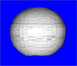
Fig.5:Reproduced shape.
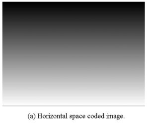
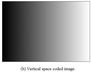
Fig.6:Two-dimensional space coded images.
CONCLUSION
In this paper, we proposed a method measuring the shape and the refractive index of transparent objects by changing background patterns.
In this experiment, space coded images of background and measured images were created using 8bit graycode patterns, respectively. And a silhouette of a spherical transparent object was extracted using the difference between a space coded background image and a space coded measured image. Then the shape of a spherical transparent object was reproduced using extracted object silhouette. So, we can measure the shape of a transparent object with the use of our proposed method.
In this paper, the shape of a spherical transparent object has been reproduced. Future work is to calculate the refractive index of transparent object using our proposed method.
REFERENCES
[1] W. Matusik, H. Pfister, R. Ziegler, A. Ngan, and L. McMillan, “Acquisition and Rendering of Transparent and Refractive Objects,” Thirteen Eurographics Workshop on Rendering, 2002.
[2] http://www.rolanddg.com/products/pix30and4.html
[3] B. K. P. Horn, and M.J. Brooks, “Shape from Shading,” Cambridge, MA:MIT Press, 1989
[4] K. keuchi, “Determining Surface orientations of specular surfaces by using The Photometric Stereo Method,” IEEE Trans. Pattern Analysis and Machine Intelligence, Vol. PAMI-3, No.6, pp.661-669, 1981.
[5] C. Lu, and S. Inokuchi, “Intensity-modulated moiré topography,” APPLIED OPTICS, Vol. 38, No. 19, pp.4019-4029, 1999
[6] D. Miyazaki, M. Saito, Y. Sato, and K. Ikeuchi, “Determining Surface Orientations of Transparent Objects by use of Polarization Degrees in Visible and Infrared Wavelengths,” Journal of the Optical Society of America A, 19(4) pp.687-694, 2002.
[7] S. Tosovic, R. Sablatnig, and M.Kampel, “On Combining Shape from silhouette and Shape from structured Light,” 1st International Symposium on 3D Data Processing Visualization and Transmission, pp.108-118, 2002
[8] N. Kazama, “Mesurement of Optical Properties and Method of Rendering for Transparent Objects.” NAIST Master’s Thesis, 1999 (in Japanese).
[9] Kosuke Sato, Seiji Inokuchi, “Three-Dimensional Surface Measurement by Space Encoding Range Imaging,” Journal of Robotic Systems, Vol.2, No.1, pp.27-39 (1985)
back